Machining and Fabrication
I enjoy making things and I know how to use tools.  I can design things such that they can be fabricated with whatever tools I have at my disposal.  I've had some very challenging machining and fabrication projects.
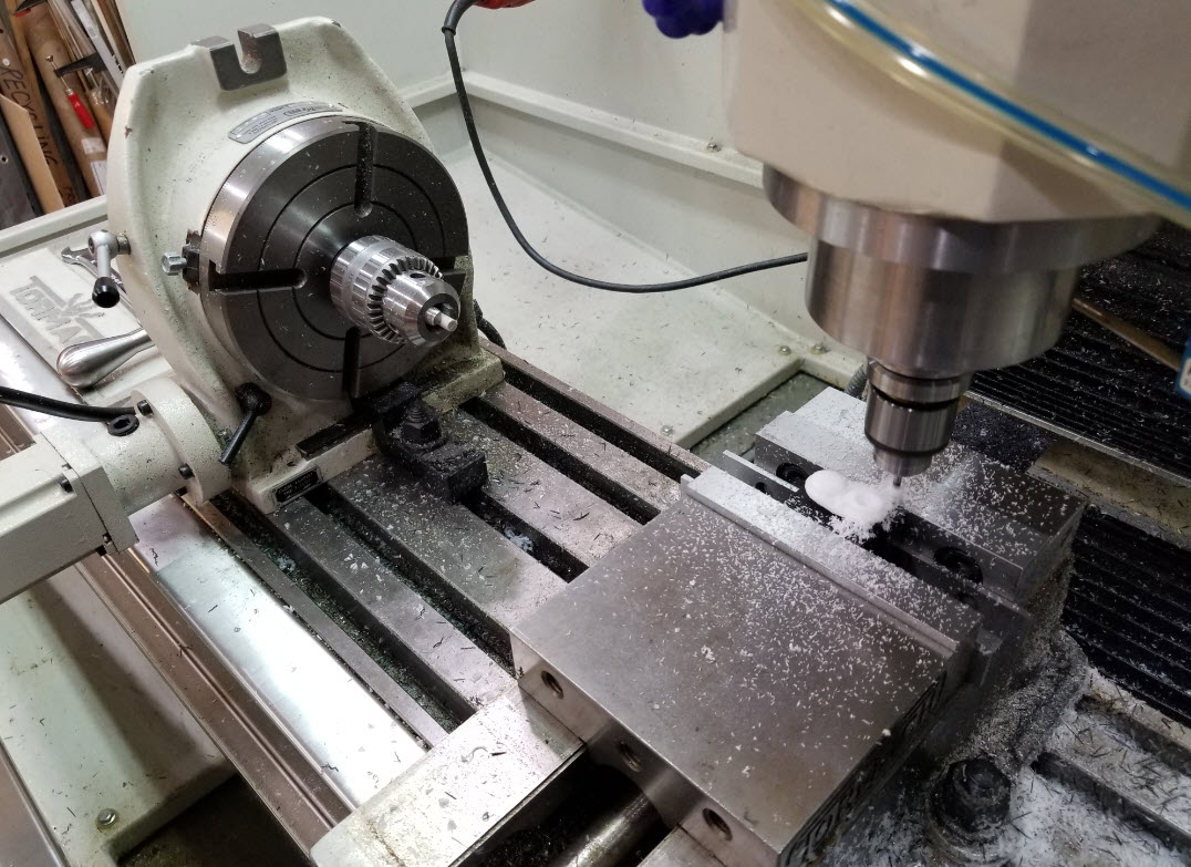
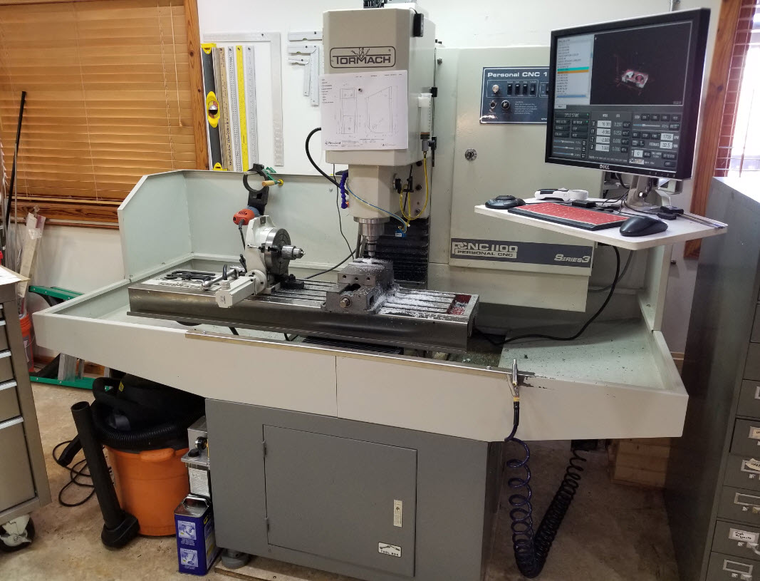
At Physcient, we have a Tormach PCNC 1100 milling machine with an integrated 4th axis, high speed spindle and power draw bar.  We also have a manual lathe with a digital read out.  I use Sprut CAM to generate G-code.  This machine is fantastic for producing our low quantity surgical instrument parts.  We have a number of very precise parts that  must have a smooth surface finish and must have fully constituted material properties and this is by far the 
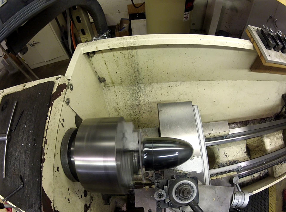
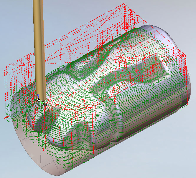
fastest, lowest cost way to produce those parts.  I use the Tormach 
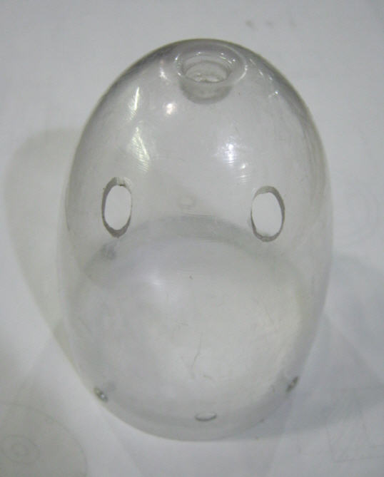
and the 4th axis to machine the Differential Dissector tips from PEEK (shown above).  This produces excellent surface finish and fully captures the performance of injection molded PEEK tips (shown below).


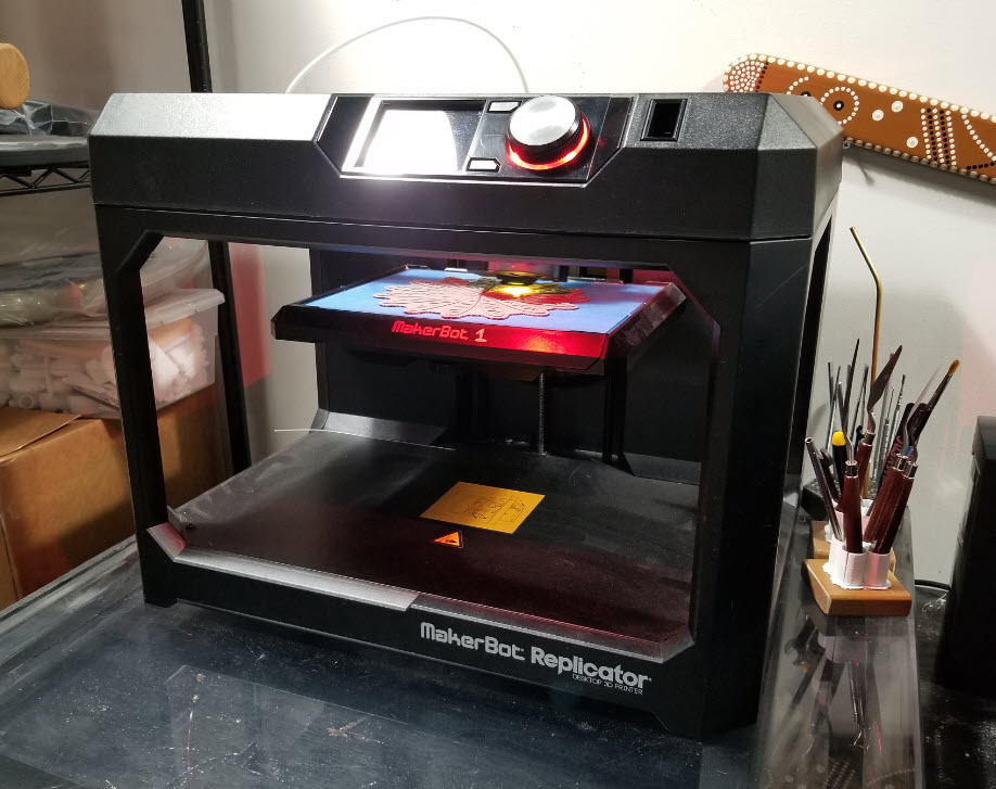
We typically use Protolabs for rapid prototyping and additive manufacturing services, but we also have a Makerbot Replicator FDM machine in our prototyping facility at Physcient.  It works well for printing handle concepts so that surgeons can stop by and quickly evaluate several designs.
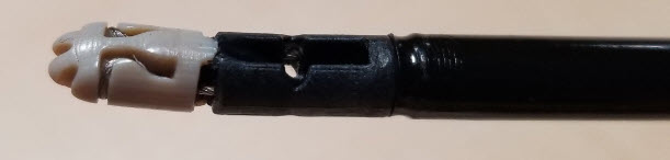
Shaft Perforation Covers right and below are Duraform PA selective laser sinter nylon.  The turquoise inserts form the silicone overmold features.  These parts have a snap latch that retain them on the shaft of the Laparoscopic Differential Dissector.  The production 
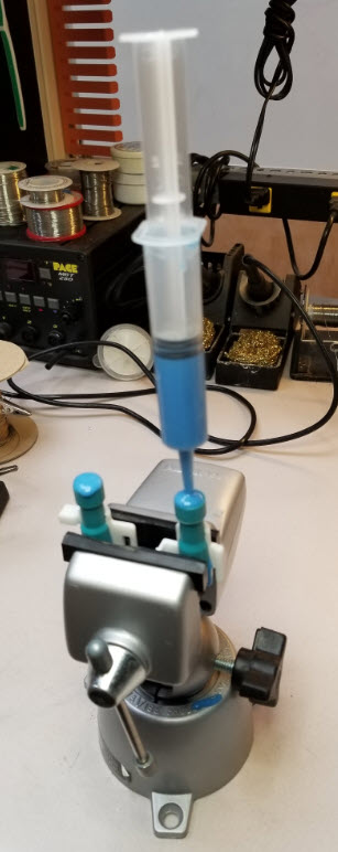
parts will be injection molded with an overmolding step.  (Right) 40 shore A durometer Silicone being injected into delrin insert that forms the overmold shaft contact and sealing features.


A frame handle seal (Above)        Silicone Button Cover (Above)
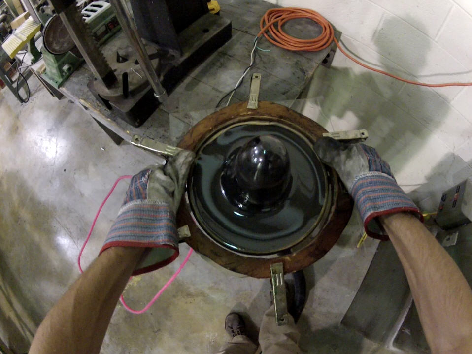
All of these molds are machined on the Tormach PCNC1100.  At Physcient, we have a mold shop where we can cast and inject a variety of polyurethane and Silicone materials. 
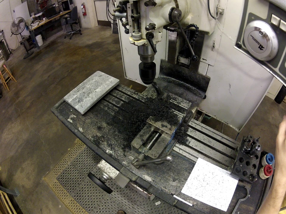
Right: This is our Partner MB 18, 3 axis CNC milling machine at iRobot.  These days, we have a full time machinist, but I've made many parts on this machine over the years.  It can be operated manually (handwheel mode), programmed via conversational mode, or programmed with G-code, written manually or generated by CAM software.
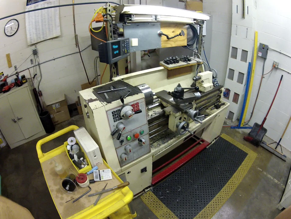
Below:  We have a 14" x 40" Jet lathe at iRobot with a DRO.
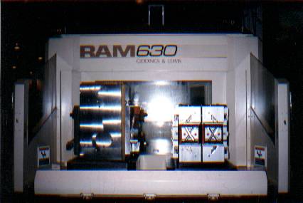
Below Right:  Giddings and Lewis RAM 630, 5 axis horizontal machine center at Volvo Construction Equipment.  I wrote G-code for this machine to cut production parts.  It's extremely fast (max feed at 1500 ipm), and uses high pressure through spindle coolant.  You have to triple check your code for this machine, and then slowly ramp up the feed % when you run parts for the first time, and parts have to be fixtured really well. 
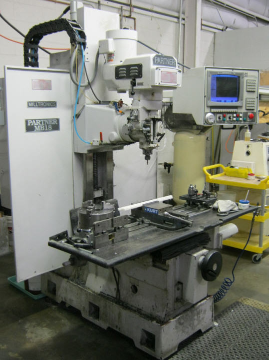


The following progression of pictures shows a process I created to form clear plastic hydrodynamic flow noses for our submersible vehicles.  Many submersible vehicles use NACA airfoil bodies of revolution to define the front of the submersible.  These shapes have low hydrodynamic drag, and there's a wealth of available lift, drag and pitching moment coefficients which are used in vehicle performance estimation and control system design.  NACA 0020 - NACA 0030 are common for submersible vehicle noses.  I created the spreadsheet below to generate airfoil coordinates.  The coordinates are used to define the nose shape in CAD.  The profile of the nose shape is split into multiple segments that can be closely approximated by multiple tangent arcs.
The multiple tangent arc segments can be programmed in G-Code for the CNC machine.  If you have a CNC lathe, this is very straightforward, and this entire process can be done with a suitable CAM system.  If you don't have a CNC Lathe, you can chuck the mold blank in the spindle of the CNC Mill, and the lathe tool in the vise and use the CNC mill as a CNC lathe as shown below left.  The program above is unique among G-code programs because it uses conditional statements to increment successive cutting passes.  Once the mold has been turned using the CNC Mill, it can be used to thermoform the nose as shown below right.  This material is PETG, it's excellent for thermoforming, has great optical clarity, and excellent impact resistance, so it makes a great flow nose for small submersible vehicles.   

Once the part has been thermoformed, the mold is chucked in the lathe (above left), and the excess material is trimmed off leaving the nose cone, exactly the right length and diameter.  The completed nose cone is shown above right and the installed nose cones are shown on the vehicles below.


CAM Software:

I can use CAM software to generate G-code to cut parts.  I had to cut this mold in 2 parts due to the 28" X axis travel of our CNC machine.  The mold is ~48" long.  The mold was used to lay up the fiberglass hulls shown to the right of the mold.  I used a program called STL Work to generate the G-Code, screen grab is shown below.


Rapid Prototype Processes:
In addition to standard machining (subtractive processes) , I've made liberal use of Rapid Prototype (additive processes) as these technologies have become more mature.  Here are 2 examples, the moving part of this vectored thruster and the flow form covers were made using selective laser sinter (SLS) rapid prototype process.  These parts are strong enough to be used directly in the submersible vehicle.  The SLS process can now be used for metal parts, and glass or carbon filler can be added to improve the strength of plastics.  These parts are made using SLS, Duraform PA.  At iRobot, we farm out rapid prototype parts to service providers, they make good parts, have quick delivery times, and we don't have to keep a rapid prototype machine maintained and operational.

ryanrun8@gmail.com

© 2020 Ryan Moody.